Getting Started with Zephyr
I recently ordered an ESP32 and found a nice RTOS called Zephyr1 to use. It’s fairly heavy - getting started with Arduino or the ESP-IDF2 appears much easier. But I am ambitious to build an OS with a few peripherals, and Zephyr has lots of modules in its tree. Further, Zephyr has support for quite a few boards, so I’m less locked into the ESP32.
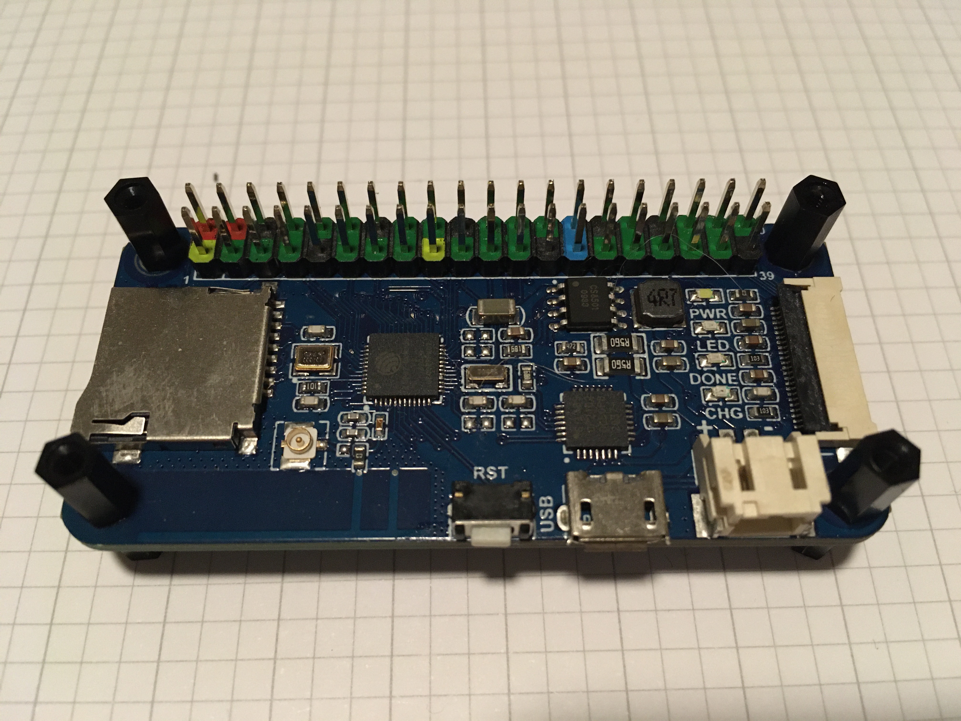
Here’s the board I’m working with, Waveshare’s ESP32-One3:
Hello World
The first program was fairly easy. After working through the getting started4 guide and specifics for the ESP325, I hit my first issue trying to build the hello_world6 program. I’ve never used cmake before, so it took a bit to sort through it, but it turns out that the ZEPHYR_TOOLCHAIN_VARIANT environment variable has lower priority than the default value. I need that to be set to espressif in order to select the right compiler for the xtensa architecture.
As an quick fix, I made this change in the Zephyr tree:
diff --git a/cmake/verify-toolchain.cmake b/cmake/verify-toolchain.cmake
index e860ecc479..b41a5dee1e 100644
--- a/cmake/verify-toolchain.cmake
+++ b/cmake/verify-toolchain.cmake
@@ -19,9 +19,9 @@
 set(TOOLCHAIN_ZEPHYR_MINIMUM_REQUIRED_VERSION 0.13.1)

 # Set internal variables if set in environment.
-if(NOT DEFINED ZEPHYR_TOOLCHAIN_VARIANT)
-  set(ZEPHYR_TOOLCHAIN_VARIANT $ENV{ZEPHYR_TOOLCHAIN_VARIANT})
-endif()
+set(ZEPHYR_TOOLCHAIN_VARIANT $ENV{ZEPHYR_TOOLCHAIN_VARIANT})

 if(NOT DEFINED ZEPHYR_SDK_INSTALL_DIR)
   set(ZEPHYR_SDK_INSTALL_DIR $ENV{ZEPHYR_SDK_INSTALL_DIR})
I later found the same issue reported on GitHub, which is now resolved.
With that patch in place I was able to build and flash the hello_world program, and I saw it printed in the serial output using minicom!
Blinky
The board has a LED connected to pin, so I figured I’d give the blinky7 program a shot as well. Zephyr doesn’t have a board configuration for this board, but it does have a guide on how to write one8. Thanks to the board vendor’s documentation about its pinouts, I know to configure the LED on pin 21 using the device tree. I just need to put the following in boards/esp32.overlay:
/ {
  leds {
    compatible = "gpio-leds";
    led0: led_0 {
      gpios = <&gpio0 21 GPIO_ACTIVE_LOW>;
      label = "LED 0 (pin 21)";
    };
  };

  aliases {
    led0 = &led0;
  };
};
This lets me extend Zephyr’s builtin device tree definition for the ESP32 with the specifics of my board.
Shields
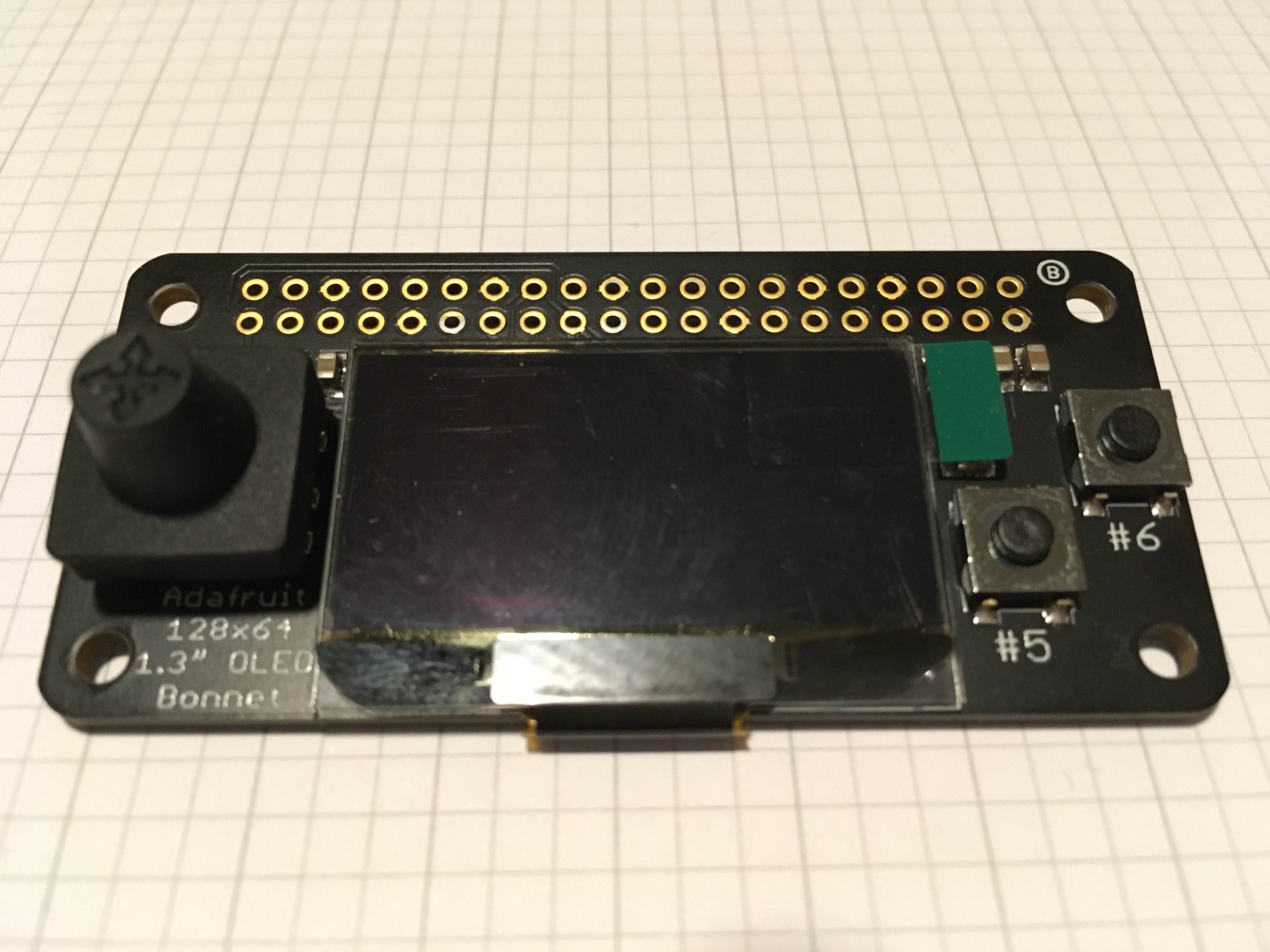
Zephyr also supports configuring shields - essentially device tree extensions that aren’t specific to the board. I bought an OLED Bonnet from Adafruit9 since it has the standard female headers for a Raspberry PI.
Following the guide to define a new shield10, I added a file named boards/shields/adafruit_128x64_oled_bonnet.overlay.
/ {
  chosen {
    zephyr,display = &ssd1306;
  };

  buttons {
    compatible = "gpio-keys";

    /* PI 29 = GPIO5  */
    /* WV 29 = GPIO34 */
    button_a: button_a {
      gpios = <&gpio0 34 (GPIO_PULL_UP | GPIO_ACTIVE_LOW)>;
      label = "A Button";
    };

    /* the rest of the buttons ... */

  };
};

&i2c0 {
  status = "okay";

  ssd1306: ssd1306@3c {
    compatible = "solomon,ssd1306fb";
    reg = <0x3c>;
    label = "SSD1306";
    width = <128>;
    height = <64>;
    segment-offset = <0>;
    page-offset = <0>;
    display-offset = <0>;
    multiplex-ratio = <31>;
    segment-remap;
    com-invdir;
    com-sequential;
    prechargep = <0x22>;
  };
};
There’s also a some Kconfig files that are required, but I won’t show those here. To write that file, I went through the exercise of mapping the ESP32’s pins to those of the bonnet. It goes like this:
- Button A of the bonnet is on GPIO 5
- GPIO 5 of the bonnet is wired to PI header 29
- PI header 29 of the microcontroller is wired to GPIO 34 of the ESP32
After doing that for each button, I was finally ready to run the display sample11. Other than using that code and project, I have to pass one extra argument to west build:
$ west build -b esp32 -- -DSHIELD="adafruit_128x64_oled_bonnet"
A Painful Upgrade
At one point while working on the shield integration, I upgraded Zephyr as documented:
$ (cd zephyr && git pull && west update)
This ran fine, pulling all the git submodules that Zephyr uses. But when I returned back to my build and flash cycle, I hit this error:
$ sudo -E west flash
...
Auto-detected Flash size: 4MB
Flash will be erased from 0x00001000 to 0x00007fff...
Flash will be erased from 0x00008000 to 0x00008fff...
Flash will be erased from 0x00010000 to 0x00033fff...
Flash params set to 0x0220
Wrote 32768 bytes at 0x00001000 in 3.1 seconds (85.6 kbit/s)...
Hash of data verified.
Wrote 16384 bytes at 0x00008000 in 1.5 seconds (87.3 kbit/s)...
Hash of data verified.
Writing at 0x00030000... (100 %)
A fatal error occurred: Timed out waiting for packet header
Further, when connecting to the board via minicom, I see it stuck in a boot loop. Here’s just the last part of boot log before it starts over again:
I (42) boot: Partition Table:
I (46) boot: ## Label            Usage          Type ST Offset   Length
I (53) boot:  0 nvs              WiFi data        01 02 00009000 00006000
I (61) boot:  1 phy_init         RF data          01 01 0000f000 00001000
I (68) boot:  2 factory          factory app      00 00 00010000 00100000
I (76) boot: End of partition table
I (80) boot_comm: chip revision: 3, min. application chip revision: 0
I (87) esp_image: segment 0: paddr=00010020 vaddr=3f400020 size=00e14h (  3604) map
I (97) esp_image: segment 1: paddr=00010e3c vaddr=3ffb0000 size=002ach (   684) load
I (104) esp_image: segment 2: paddr=000110f0 vaddr=3ffb02ac size=00104h (   260) load
I (112) esp_image: segment 3: paddr=000111fc vaddr=40080000 size=00400h (  1024) load
I (121) esp_image: segment 4: paddr=00011604 vaddr=40080400 size=02e58h ( 11864) load
I (134) esp_image: segment 5: paddr=00014464 vaddr=00000000 size=0bbb4h ( 48052)
E (155) esp_image: invalid segment length 0xffffffff
E (156) boot: Factory app partition is not bootable
E (156) boot: No bootable app partitions in the partition table
I have no intuition for either error, but clearly the firmware and/or software isn’t completely making it to the board. From the searching I did, it seems quite common for some (mostly older) ESP32 chips. There are suggested fixes varying from shorting GPIO 0 to adding in capacitors across some pins. My approach was to start simplifying the problem - it’s difficult to sort through all the steps that west and cmake are executing, but I know that somewhere underneath those abstractions is the ESP-IDF.
After working through the getting started guide for the ESP-IDF, I have a new python virtual environment that can run the upstream esptools. Then I disect the command that west flash was executing, but replacing the esptool.py path to my alternate copy:
${HOME}/.espressif/python_env/idf4.3_py3.10_env/bin/python ${HOME}/dev/esp-idf/components/esptool_py/esptool/esptool.py -p /dev/ttyUSB0 -b 460800 --before default_reset --after hard_reset --chip esp32 write_flash --flash_mode dio --flash_size detect --flash_freq 40m 0x1000 ${HOME}/dev/esp32-one/build/esp-idf/build/bootloader/bootloader.bin 0x8000 ${HOME}/dev/esp32-one/build/esp-idf/build/partitions_singleapp.bin 0x10000 ${HOME}/dev/esp32-one/build/zephyr/zephyr.bin
With this change I can flash the board again. I also ended up finding a bug report12 that corroborates my findings. I did find it a bit disheartening that Zephyr’s fork13 is pretty far behind and seems to have diverged. I didn’t spend much time on it, but I wasn’t able to easily update that module in zephyr/west.yml to point to the original.
Results
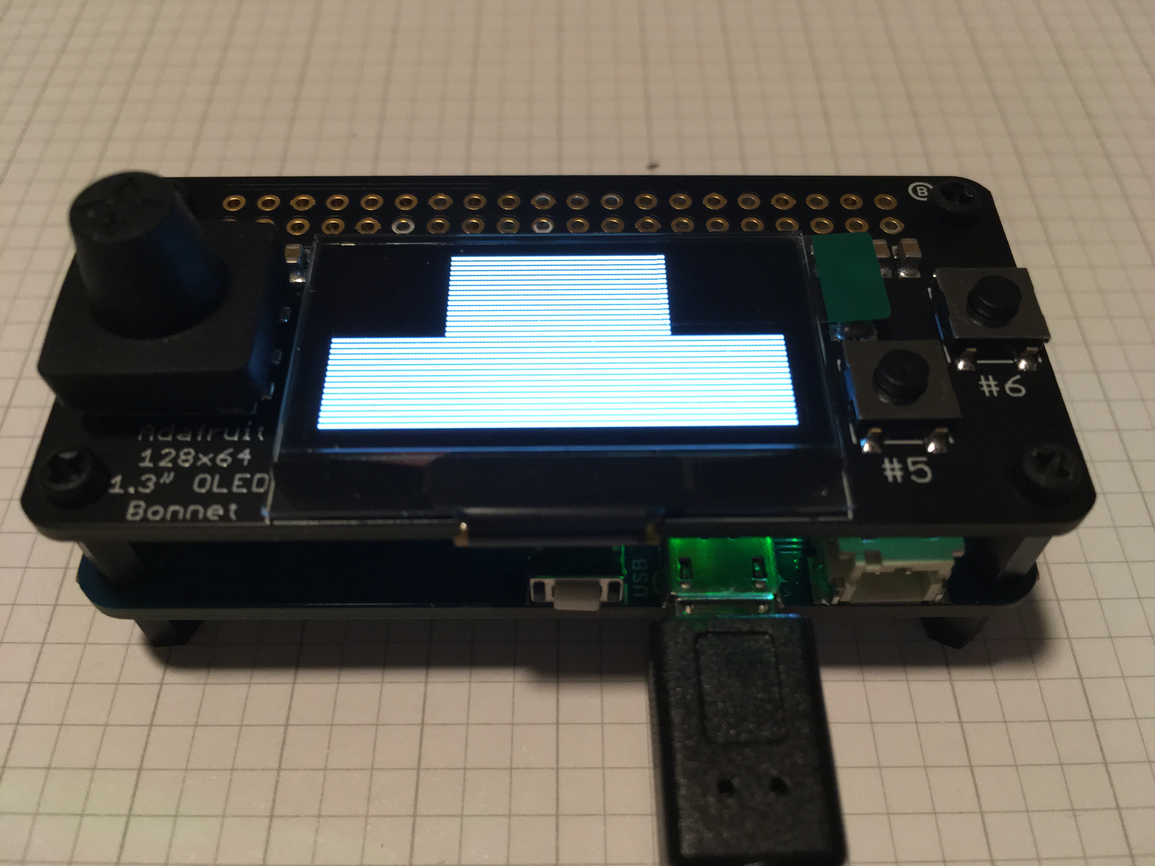
It’s not quite right - there are supposed to be boxes of a few different colors. But it feels nice to be past the tooling and configuration and be able to write some code.
-
https://docs.zephyrproject.org/latest/getting_started/index.html#getting-started ↩︎
-
https://docs.zephyrproject.org/latest/boards/xtensa/esp32/doc/index.html ↩︎
-
https://github.com/zephyrproject-rtos/zephyr/tree/main/samples/hello_world ↩︎
-
https://github.com/zephyrproject-rtos/zephyr/tree/main/samples/basic/blinky ↩︎
-
https://docs.zephyrproject.org/latest/guides/porting/board_porting.html ↩︎
-
https://docs.zephyrproject.org/latest/guides/porting/shields.html ↩︎
-
https://github.com/zephyrproject-rtos/zephyr/tree/main/samples/drivers/display ↩︎